25+ dc power supply block diagram explanation
A complete tutorial of 555 Timer IC with its block diagram working of SENE 555 TimerPin Configuration and pin out diagram Download 555 data sheet. Like other power supplies an SMPS transfers power from a DC or AC source often mains power see AC adapter to DC loads.

7805 Circuit Dc Regulated Power Supply
The first stage converts the ac supply into dc and the second stage converts the dc voltage to the desired dc output voltage.

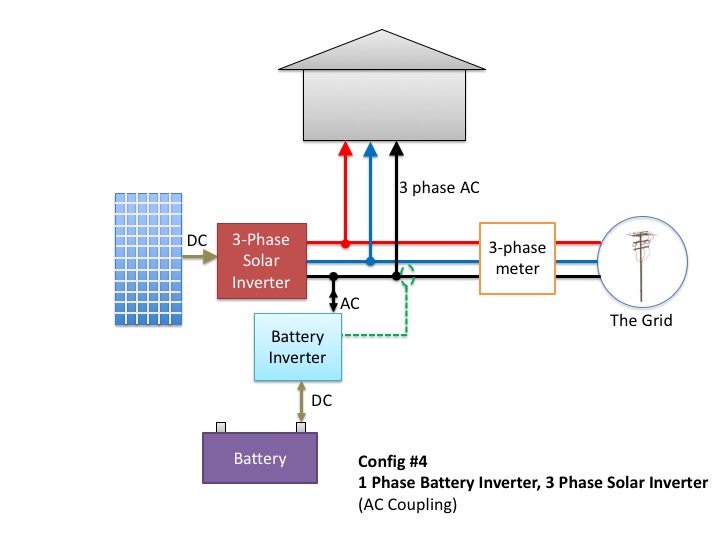
. Generally before Power Amplifier the signal is corrected using Pre Amplifiers and Voltage controls amplifiers. But I wanted to sketch a simple basic solar power system diagram that shows the building blocks. Circuit Symbol Wire Color Codes May 23 2021 August 1.
A typical block diagram of PLC consists of five parts namely. 12V 10A switching power supply with schematic and explanation Ⅱ The Basic Principle of Switching Power Supply 21 The Basic Principle of PWM Switching Power Supply. A switched-mode power supply switching-mode power supply switch-mode power supply switched power supply SMPS or switcher is an electronic power supply that incorporates a switching regulator to convert electrical power efficiently.
The basic building blocks of its major components. A simplified block diagram representing the internal circuitry of the 555 timer is given below with a brief explanation of each of its connecting pins to help provide a clearer understanding of how it works. Solar power systems vary widely in their power producing capabilities and complexity.
Power supply for this project TIP 142 147 Internal diagram and pin out. Now that weve covered the signal flow Ill go back and cover the other amplifier components that I didnt mention. Wall plug power of 120 volts AC USA or 100 220 or 240 volts AC in other countries runs to the fuse F1Fender guitar amp fuses are MDL type slow blow or time delay size 3AG 14 inch 6mm wide by 1 14 inch 30mm long.
April 25 2021 April 28 2021. A switched-mode power supply SMPS is a power electronics topology which consists of two power stages. Depending on the manufacturer the standard 555 timer package includes 25 transistors 2 diodes and 15 resistors on a silicon chip installed in an 8-pin mini dual-in-line package.
This power supply is only enough for powering one channel and for stereo applications double the current ratings of the transformer diodes and fuses. FUNCTIONAL BLOCK DIAGRAM 00585-001 AD9288 TH REF TH ADC OUTP UT RE GIS T E R 8 8 8 OUTP UT RE GIS T E R TIMING TIMING VDD. November 25 2016 Ligo George Electronics.
Block Diagram Explanation. It is the simplest form of electrical drawing as it only highlights the function of each component and provides the flow of process in the system. It is made by many companies in the original bipolar and low-power CMOS types.
715 and 716 present the block diagram of the SMPS. For the sake of explanation I omitted Buffer Register. 3 Digital supply current based on V.
Uninterruptible Power Supply UPS. December 24 2012. 4 Ohms 100 Watt speaker.
A block diagram is a type of electrical drawing that represents the principle components of a complex system in the form of blocks interconnected by lines that represent their relation. Power supply for this circuit. According to an estimate a billion units were manufactured back in the year 2003 alone.
In a linear power supply the power transistor is operating in a linear mode. Regardless of a given systems capacities and specifications theres a common thread among most of them. Power Supply Rejection Ratio PSRR 25C I 8 20 8 20 8 20 mVV.
The device can operate over the 40 to 85 C. Today the SMPSs provide power to the following equipment. A 40-40 unregulated dual supply for powering this amplifier project is shown below.
Resistive Capacitive. An ac load of 10 pF or a dc current of 40 µA. TransformerLess Low Cost DC Power Supply.
It is quite easy to understand the working process of the switching power supply. Formula Derivation Examples. C Page 4 of 24.
Programmable Logic Controllers continuously monitors the input values from various input sensing devices eg. The power of the DCDC converter depends on the characteristics of the vehicle such as top speed acceleration time from 0 to 100 Kmh weight maximum torque and power profile peak power continuous power Büchi et al 2006. It can be noticed that the use of high power DCDC converters is necessary for EV power supply system.
72 volts is the nominal input voltage for light-save driver and I could have used 10 volt or 16 volt rated MLCCs but I chose a 10 micro-FED part rated at 25 volts and then the 12-10 case size because higher voltage ratings and bigger physical size are both inversely proportional to the capacitance loss. This is the power supply pin and for general purpose TTL 555 timers is between 45V and 15V. The Si4010 is a fully integrated crystal-less CMOS SoC RF transmitter with an embedded CIP-51 8051 MCU.
Accelerometer weight scale hardwired signals etc and produces corresponding output depending on the nature of production and industry. SPI Communication Module Block Diagram. February 24 2012 September 5 2021.
As you can see in the above block diagram Power Amplifier is the last stage which is directly connected to the load. Resistor 14 th. A 555 timer can also be used in dc-dc converters digital logic probes.
It acts as an interface between user processor programmer and SPI. The loss of capacitance with DC bias. 40V Rail to Rail power supply with 40V GND -40V power track output.
It operates from a wide range of power supplies ranging from 5 Volts to 18 Volts supply voltage.

Power Supply Classification And Its Various Types

Here This Circuit Diagram Is For 12v Regulated Fixed Voltage Dc Power Supply These Power Supply Circuit Power Supply Circuit Circuit Diagram Power Supply

How Many Types Of Powe Supplies Working Features And Applications

Power Supply Classification And Its Various Types

Simple 1a 12v Smps Full Circuit Diagram With Explanation Power Supply Circuit Circuit Diagram Electronics Circuit

Transformerless Power Supply Construction Working And Its Types

Power Supply Classification And Its Various Types

Lm2576 Based Nc Adjustable Switching Power Supply Design

7805 Circuit Dc Regulated Power Supply

Simple 12v Fixed Voltage Power Supply Circuit Diagram Diagram Circuit Power Supply Circuit Circuit Diagram Power Supply

Pin On Diagramas

Uc3845 Current Mode Pwm Controller Pinout Feature Datasheet

Power Supply Classification And Its Various Types

12v Dc Power Supply Circuit Diagram Circuit Diagram Power Supply Circuit Electronics Circuit

Don T Add Batteries To A 3 Phase Home Before Reading This
How To Convert Pure Dc To Pulsed Dc Quora

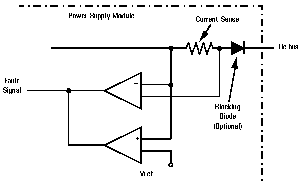
Kepco Inc Redundancy And Hot Swapping